Routing Airflow
(Last edited 5/14/2026)
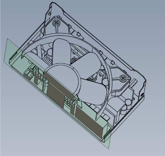
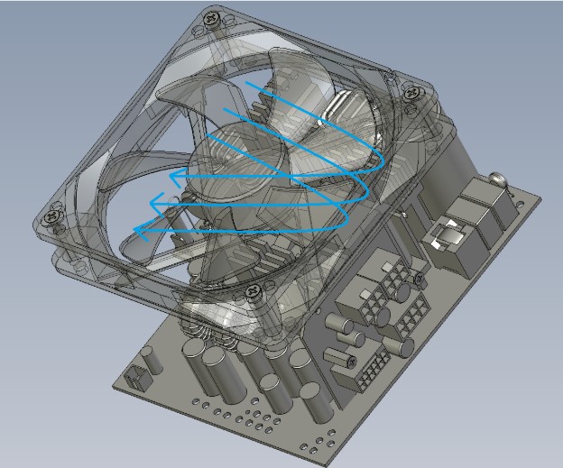
The cutaway shown above reveals the main transformer's position relative to the fan hub, highlighting why minimizing hub size and managing the direction of airflow is critical.
Since air always follows the path of least resistance, the fan's output won't fully reach all of the critical components of your power supply without help.
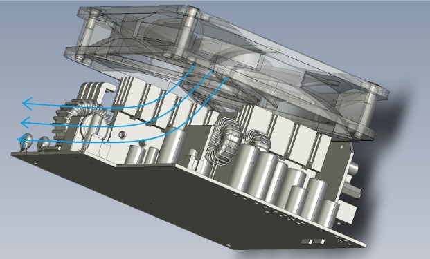
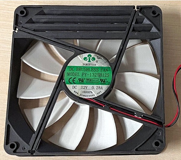
In the below example, we can see how a good portion of the air from the fan can escape right out of the exhaust on the back of the PSU:
Ideally, we want to force the air towards the components at the front of the PSU to cool the components located there before exhausting out of the back. To do this, we use baffles.
By installing baffles, we can guide the cooling current precisely where components need it most, ensuring efficient temperature management.
An example of a typical power supply baffle looks like this:
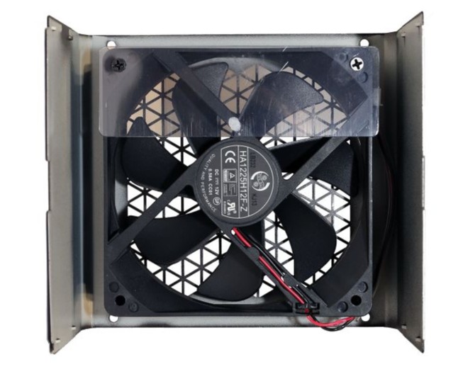
This clear Mylar baffle covers the PSU's exhaust side, preventing air from escaping prematurely and redirecting airflow toward the front. This design ensures the main transformer and other components receive adequate cooling rather than "suffocating" beneath the fan hub and towards the front of the PSU.
Below is an example of how the airflow should occur once the baffle is installed:
Louvers offer an alternative air diversion method—one I find more elegant despite its rarity in modern designs:
Unlike baffles that block airflow completely, louvers guide air more subtly. Their decline in popularity likely stems from improved airflow simulations revealing they allowed excessive exhaust leakage.
Baffle designs vary considerably based on specific airflow requirements. The one shown below is used in a power supply with a planar transformer. The unique design also solved a problem where the AC inlet was getting too hot.
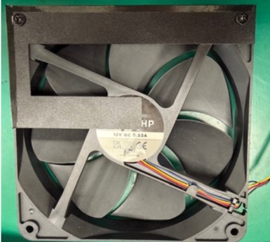
Another aspect of cooling the PSU is the fan’s blade design. While a fan with better static pressure (measured in mmH₂O) is preferred over one with higher airflow (measured in CFM), the fan still needs a good balance between the two. Inside a PSU, the fan is operating against a restrictive flow path (heatsinks, transformers, etc). This creates static pressure (back pressure). When airflow demand and fan capability are mismatched, several things can happen. There can be an increase in aerodynamic loading on the fan blades, a shift in the operating point on the fan P‑Q curve, an excitation of the blade pass frequency (BPF) or harmonics and an exposure of resonance in the impeller. This is why fan specs and PRDs explicitly require the fan to maintain RPM within ±10% regardless of pressure and define static pressure at zero flow to ensure stable operation under PSU‑internal restrictions.
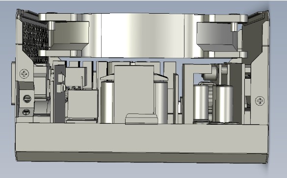
The below side view illustrates the proximity of the fan to the components and how a fan with the right balance of both mmH₂O and CFM can be effective and quiet.