The Difference Between a Rod Core Inductor and a Toroid Coil
(Last edited 5/14/2026)
The term "toroid" refers to a doughnut shape. Toroidal inductors feature copper wire wrapped around a doughnut-shaped ferrite or powdered iron core. This design contains the magnetic field almost entirely within the core in a closed loop, resulting in minimal EMI. The downside? They consume considerably more space.
A rod core inductor consists of copper wire wrapped around a straight ferrite or iron rod. Since the magnetic field isn't fully contained within the core, some of it extends beyond the rod, so these inductors tend to emit more electromagnetic interference (EMI).
I've also noticed these inductors produce more annoying noises than toroid inductors. As the magnetic field fluctuates, it physically bends and vibrates the rod, creating unwanted noise.
Manufacturers choose rod cores primarily for their affordability and compact size. They'll fit in tight spaces where toroidal inductors simply won't. Still, I avoid them whenever possible.
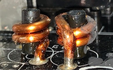
Here is an example of a pair of rod core inductors inside a PSU
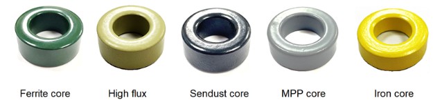
Using Sendust as a Ferromagnetic Material for Inductors
Sendust is a magnetic alloy that was created as an alternative to iron powder and other magnetic core materials used in inductors and transformers. It is made up of 85% iron, 9% silicon, and 6% aluminum.
Sendust is highly regarded because it has lower eddy current losses and does not produce mechanical vibrations when exposed to magnetic fields. In our industry, the primary drawback is its cost. Additionally, since Sendust is a sintered compound, it tends to be more brittle than other materials. Consequently, Sendust inductors might need to be slightly larger to match the energy storage capacity of an iron core, so space limitations in smaller designs should be taken into account.
I’ve been using Sendust almost exclusively for over 10 years. I’ve found that the small investment made to improve audible noise is well worth it as customer complaints have been reduced significantly.
Split-Windings as Opposed to Single-Windings
Once again, we have an optimal solution that requires additional space. However, if space permits, I highly recommend using split-windings.
As the term suggests, a single-wound inductor consists of a single continuous copper wire coil wrapped around the core. A split-wound inductor, also called a bifilar-wound or common-mode choke, divides the copper wire into two separate windings around the core. This configuration effectively blocks common-mode noise, making it perfect for use as a PFC choke since it helps reduce EMI and RFI. Common-mode noise often arises from parasitic capacitances between the MOSFETs and ground.
Even though the split-wound inductor is larger, its cost should not significantly exceed that of a single-wound inductor, provided the manufacturing plant uses an automated process to produce them.
We started using the split-wound inductor for our PFC chokes when we started to see some high-frequency RFI results in some of our designs. Unfortunately, due to the slightly larger size, we can’t use them in smaller form factors like SFX.