Disadvantages and Advantages of Cable Modularity
(Last edited 5/30/2026)
We’ll touch on the subject of resistance again later, but as it applies to modular connectors, resistance is a key factor when considering the negatives of modular connectors. More than anything, issues that arise are caused by user error; if not poor quality control of the cable itself Often, connectors are not fully inserted, or terminals are damaged. Beyond these weaknesses, modular designs offer numerous advantages.
Consumers benefit from modularity by allowing them the ability to install only necessary cables for their specific configuration. Manufacturers, despite the additional costs of modular interface PCBs and connectors, enjoy streamlined assembly with fewer opportunities for error. The modular PCB design also creates valuable space for additional filtering components.
One major disadvantage of modularity that needs to be discussed is the lack of standardization across the several brands on the market. In fact, not only do many brands have different pin-outs on the connectors on the PSU side of the cable, but often times one will see different pinouts of cables withint the same company's power supplies! Sometimes intentionally. Sometimes accidently.
It is very important that cables from different power supplies, especially different power supply brands, not get mixed up. Doing so can actually destroy hardware as you could send the wrong voltage to that hardware. When in doubt, always, always, always use a multimeter to tap out the outputs of the power supply's connectors and then check the continuity of the connectors on each side of the cables.
Fixed-cable designs might appear simpler and more economical at first glance. Yet considering their labor-intensive assembly with each wire manually inserted into the PCB and needing to be held in place throughout wave soldering, it is surprising they persist in today's market. These units typically appear in budget-oriented power supplies, which already run hotter due to lower efficiency, further complicated by crowded component layouts.
Semi-modular designs represent the worst compromise: combining the tedious wire insertion and cramped PCB layout of fixed cables with the higher material costs of modular systems. This hybrid approach delivers few benefits and, in my opinion, should be phased out entirely.
Understanding Cables, Wires, Terminals and Connectors
Never in my twenty years building power supplies have I obsessed over cables like I have lately. Two things keep me up at night: those melting 12V High Power connectors on premium GPUs making the news7, and copper prices climbing through the roof.
I'm fighting a constant battle with our Chinese suppliers who keep pitching cut-rate components that I wouldn't even consider putting in a $30 power supply. When the finance team starts eyeing these "cost-saving opportunities," I get genuinely concerned.
Just recently, a vendor showed us connectors costing half what we normally pay—missing the crucial UL 94 V-0 fire rating. This may not sound like a big deal, but it only takes one customer’s computer to have flaming bits of plastic dripping everywhere to open up a very expensive lawsuit.
Another supplier seriously suggested copper-clad aluminum wire. Yes, it was 16 AWG, but aluminum conducts 40% worse than copper. You'd need to jump to 14 AWG just to break even on performance. Another downside of aluminum is that it doesn’t have the memory of copper. Copper can be bent back and forth almost indefinitely and not break. Aluminum, however, can only be bent so many times before it breaks.
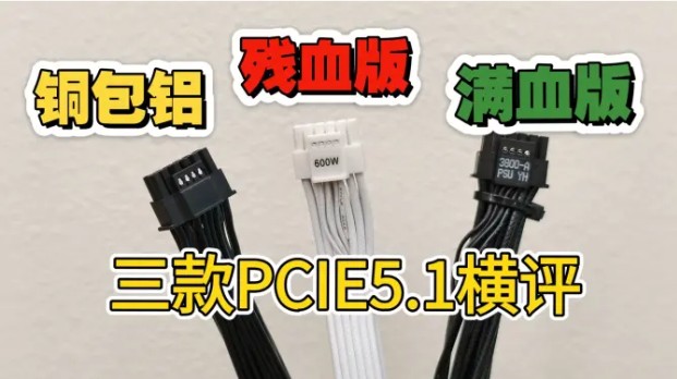
This user found copper clad aluminum wires in his PCIe cables! Higher temperatures and lower voltage! https://www.bilibili.com/video/BV1kWgkzAESU/
Even terminals demand scrutiny. From the beginning, we've examined their materials, design, and both the terminal and crimp quality with meticulous care. In fact, we “borrowed” this crimp quality guideline poster from TE and give it to all of our engineers:
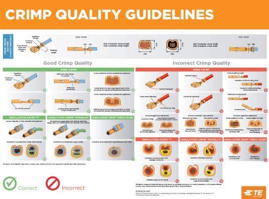
This crimp quality guideline “poster” can be found in PDF format here.
Material selection for terminals varies significantly. Brass terminals offer superior electrical conductivity compared to phosphor bronze options, which typically handle less current, due to the use of zinc versus tin in the alloy.
The reason phosphor bronze exists is due to its durability. Tin strengthens the copper’s matrix. Phosphorus improves grain structure and wear behavior. This results in much better resistance to loss of contact force over time, especially at elevated temperatures. While brass deforms and relaxes under repeated stress, phosphor bronze survives hundreds of mating cycles with stable force versus tens.
For applications requiring exceptional current capacity and durability, specialized "high-current system" terminals exist. Though visually similar to standard brass versions, these incorporate crucial modifications that minimize resistance and heat generation. Their composition features enhanced copper content, while the plating incorporates gold elements with nickel underlayment—refinements absent in conventional terminals. These engineering improvements yield a substantial performance boost, accommodating an additional one to two amps per connection point.
And then we have all of the drama over springs, dimples and the amount of play in the connectors…