Why a UPS Without a Pure Sine Output May or May Not Be An Issue
(Last edited 10/10/2026)
Part One: How a Simulated Sine Wave UPS Differs from Utility Power
Electric utilities deliver AC power in the form of a sine wave. The voltage changes continuously from positive to negative polarity, passing smoothly through every voltage level between its positive and negative peaks.
A battery-powered UPS cannot directly reproduce this waveform without additional circuitry. Producing a clean sine wave requires sophisticated pulse-width modulation, filtering, and power electronics, which add cost and complexity. As a result, many consumer and entry-level UPS products generate what is commonly called a "simulated sine wave" or "stepped sine wave."
Rather than producing a continuously changing voltage, these UPS units approximate a sine wave using a series of flat voltage steps. Some lower-cost designs produce a waveform that is nearly square, switching abruptly between positive voltage, zero voltage, and negative voltage.
A true sine wave and a simulated sine wave may have the same RMS voltage and frequency, but they reach those values very differently.
With a true sine wave:
- Voltage changes continuously.
- Peak voltage exists only momentarily.
- Zero crossings occur instantaneously.
- The rate of voltage change is smooth and predictable.
With a simulated sine wave:
- Voltage remains at some levels longer than a sine wave would.
- Voltage transitions occur more abruptly.
- Flat regions may exist near the peak or near zero.
- Harmonic content is substantially higher.
To many electrical devices these differences are irrelevant. A heater, incandescent bulb, or resistive load generally only cares about RMS voltage. Modern switchmode power supplies, however, actively monitor and interact with the incoming waveform, which is where compatibility concerns can arise.
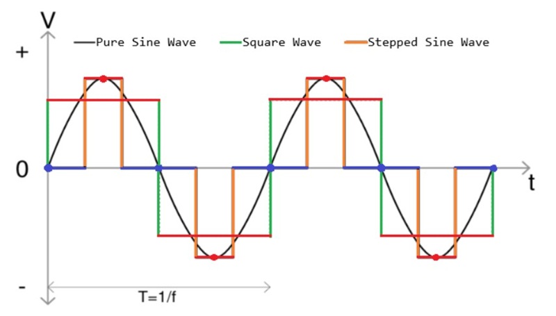
In the above drawing, I’ve made the peaks of the sine waves red (lines and dots) and the zero intersections blue. As you can see, the square wave and stepped sine wave linger at the peaks far too long compared to the pure sine wave.
Part Two: Why Active PFC Power Supplies May Object
Most modern computer power supplies use Active Power Factor Correction (Active PFC). The purpose of the PFC stage is to force input current to follow the shape of the incoming AC voltage.
Under normal utility power, the controller expects to see a smooth sinusoidal voltage. The current reference it generates is based on that expectation.
When operating from a simulated sine wave UPS, the controller suddenly encounters a waveform with long flat regions, abrupt transitions, and significantly higher harmonic content.
Importantly, the controller does not "know" it is connected to a UPS. It simply analyzes the waveform presented at its input and attempts to determine whether line conditions are normal.
Certain controllers, particularly older designs, may interpret aspects of the waveform as evidence of an abnormal power condition:
- Extended periods near zero volts may resemble a brownout.
- Missing voltage transitions can resemble a dropout or missing half-cycle.
- Abrupt voltage steps can appear as line disturbances.
- Unexpected harmonic content may cause the controller's internal calculations to deviate from expected operation.
If the controller concludes that the input power is outside its acceptable operating window, it may shut down the power supply.
This behavior is not the power supply failing. It is the protection system functioning as intended.
The power supply is essentially saying:
"The AC input no longer resembles a valid utility source. To protect the power supply and the connected equipment, operation will be suspended until acceptable input conditions return."
This is why some users experience an immediate computer shutdown when their UPS switches to battery power, even though the UPS itself is functioning normally.
The issue is not that the UPS lacks sufficient power capacity. Rather, the power supply and UPS disagree about what constitutes acceptable AC input.
Part Three: Could a Simulated Sine Wave Actually Damage a PSU?
This is where misinformation often appears online.
In most cases, the answer is no.
A modern power supply that is incompatible with a simulated sine wave UPS typically shuts down. It does not continue operating itself into destruction.
However, there is a theoretical mechanism that has led some engineers to express concern.
Active PFC circuits contain large bulk capacitors immediately after the rectifier and boost converter. These capacitors must absorb and release energy as the AC waveform changes.
A simulated sine wave contains significantly more harmonic content than a true sine wave. Those harmonics can increase ripple current within various power-stage components, including the bulk capacitors. And ripple current creates heating.
The heating mechanism is straightforward:
As ripple current increases, internal capacitor heating rises according to the square of that current.
Higher internal temperature accelerates electrolyte evaporation and dielectric degradation. Over very long periods, this can shorten capacitor life.
It is important to keep this concern in perspective.
A correctly designed power supply should already include substantial capacitor margin. The occasional operation from a simulated sine wave UPS is not expected to damage quality power supplies.
The greater concern historically involved lower-cost designs with marginal component selection and insufficient thermal headroom.
Part Four: Why Modern High-End PSUs Are Generally Unaffected
The concern over simulated sine wave UPS compatibility largely originated during the transition from passive PFC and early active PFC designs to today's more sophisticated controllers.
Most premium power supplies released during the last decade use advanced average-current-mode PFC controllers.
These controllers continuously monitor the instantaneous rectified input waveform rather than relying solely on assumptions about a sinusoidal input shape.
As a result, current demand can be adjusted dynamically to match the incoming voltage regardless of whether that waveform is a perfect sine wave or an approximation.
Digital PFC controllers extend this capability even further by actively analyzing the behavior of the input waveform and adapting their control algorithms in real time.
As a result, modern premium power supplies are far less likely to misinterpret UPS-generated waveforms as fault conditions.
Additionally, Corsair specifies bulk capacitors with significant reliability margin.
For example:
- Higher ripple-current ratings.
- Longer lifetime ratings.
- Higher temperature capability.
- Lower ESR characteristics.
This means that even if a simulated sine wave UPS increases ripple current somewhat, the components remain well within their intended operating limits.
For this reason, compatibility problems with modern premium power supplies have become increasingly uncommon.
Appendix: Why Does My PSU Buzz on Battery Power?
Some users notice that their power supply becomes noticeably louder when a UPS switches from utility power to battery operation.
In most cases, this sound originates from the PFC inductors rather than from any dangerous electrical condition.
Magnetic components physically change shape slightly when exposed to changing magnetic fields. This phenomenon, called magnetostriction, causes the core and windings to vibrate.
A pure utility sine wave produces relatively smooth magnetic forces.
A simulated sine wave contains abrupt transitions and additional harmonic frequencies. These harmonics create more complex magnetic forces within the PFC choke.
As a result, small mechanical vibrations that were previously inaudible may become large enough to hear.
A newer PSU may actually exhibit more audible noise than an older design because:
- Larger inductors store more energy.
- Dual-PFC arrangements contain more magnetic components.
- Modern converters operate across a wider range of operating modes.
- Certain harmonics may fall directly within the audible frequency range.
The presence of buzzing does not necessarily indicate a fault.
In most cases, the power supply is operating normally and the user is simply hearing magnetic components responding to the altered UPS waveform.