Secondary Rectification and Filtering
(Last edited 5/14/2026)
The next step involves converting the high-frequency AC from the main transformer back to DC. This conversion process uses different rectification methods: "Passive," "Synchronous," or "Semi-Synchronous." Each method employs different components. Passive rectification relies on Schottky diodes, synchronous uses transistors (MOSFETs or GaNFETs), while semi-synchronous combines both approaches.
Though I've successfully used Schottky diodes for secondary side rectification, transistors deliver significantly better efficiency. Simply switching from diodes to transistors can upgrade a power supply from Bronze to Gold efficiency rating. And as of very recently, you can actually obtain MOSFETs that can do the same job as Schottky diodes for about the same price if you don’t include the cost of the driver IC.
Some transformers feature multiple output windings (+12V, +5V, +3.3V) with separate rectification for each; A technique called "independent regulation." While this was standard in quality power supplies about ten years ago (alongside cheaper alternatives we'll discuss later), modern designs rarely use multiple transformer outputs.
What the secondary rectification stage accomplishes is regulation of conduction timing. Conduction timing is the exact time interval during each switching cycle when current is allowed to flow from the transformer secondary into the output filter.
It’s also important to point out the common misconception that the secondary rectification regulates the output voltage. This regulation is done on the primary side by the PWM controller adjusting the duty cycle and switching frequency. The precise output voltage is maintained by a feedback loop between a sensor and reference voltage and the primary side’s PWM controller. There’s more on the control and feedback circuit later in this e-book.
Once rectified, the DC output requires smoothing to eliminate voltage ripple. This is accomplished using inductors (which resist current fluctuations) and capacitors (which stabilize voltage).
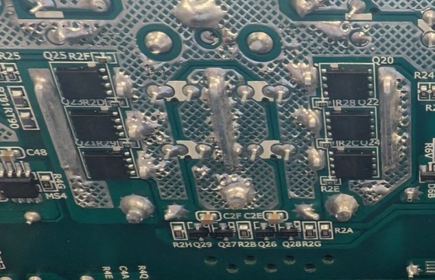
The bottom of this be Quiet Pure Power 13M 1000W is where you’ll find the SR MOSFETs.
Group regulation refers to a design approach where multiple output rails share a common regulation mechanism. Instead of each rail having its own independent feedback loop and control, there is only a single feedback loop regulating the entire group.
The main transformer will have windings for +12V, +5V and +3.3V, and each output is rectified and filtered independently, but the feedback circuit is only monitoring one of these rails. This is why we tend to have the phenomenon called “cross-loading”. The other rails “track” the regulation of the one monitored rail, but if the load on one of those rails are lower or higher than the designer’s expectations, the voltages of one or more rails may kilt a bit out of specification.
Modern power supply design has largely moved beyond both group and independent regulation approaches. The traditional method of using multi-winding transformers with separate rectification circuits for each output voltage proves both costly and spatially inefficient compared to contemporary alternatives. Today's compact DC-to-DC conversion circuits (sometimes abbreviated as "D2D") can efficiently step down a single +12V rail to produce the necessary +3.3V and +5V outputs, offering significant advantages in both cost and space utilization. I'll explore these DC-to-DC converters in greater detail shortly