Why Does The Inrush Current Relay Make a Click Noise?
(Last edited 5/14/2026)
First, let’s explain in greater detail what the function of the relay is…
When an SMPS is first powered on the bulk capacitors are not charged. They look almost like a short circuit to the AC line. This can cause extremely high peak current (tens or hundreds of amps for a few milliseconds). Uncontrolled inrush current can blow fuses or trip breakers, stress rectifiers, capacitors, and EMI filters, increase EMI and reduce reliability.
The inrush current relay is used to limit the large surge of current of mains power that flows when the PSU is first switched on, and then remove that limitation once normal operation is established. At power‑on, the relay is open, forcing current to flow through a current‑limiting element, typically a power resistor or an NTC thermistor. This limits the charging current of the bulk capacitors to a safe level. After a short delay (usually 100 ms to a few seconds), once the bulk capacitors are charged, and the PSU control circuitry is up and running, the relay closes, shorting across the resistor/NTC. This eliminates unnecessary power loss, prevents heating of the limiter and improves efficiency during steady‑state operation.
Most of the time, this is a mechanical relay, and it usually makes an audible “click.” What you’ll hear (and when) is one click shortly after power‑on. This is the relay closing to bypass the inrush‑limiting resistor or NTC once the bulk capacitors are charged. Sometimes a click at power‑off. That’s the relay opening again as power is removed. The click typically happens a fraction of a second to a few seconds after you turn the device on, depending on the design.
Not every PSU will make a clicking noise. A cheaper or very low power PSU may have no relay at all. Some PSUs may use a MOSFET as an inrush limiter. At startup, the MOSFET behaves like a variable resistor that starts “large” and gradually becomes “small.” Once the PSU is powered on the MOSFET is partially on and it limits current. After the capacitors are charged, the MOSFET is fully on and there is very low loss. While you avoid the click noise with a MOSFET, you incur higher cost, run into some thermal challenges.
Power Rectification
A term I haven’t used yet, but is a common term pertaining to this e-book, is “switch-mode”. Often, the type of power supply used in a computer is called a “SMPS” or “switch-mode power supply”. This type of power supply is used in most (almost all6) power supplies that convert AC to DC. Even phone chargers. This name comes from how these units rapidly switch electrical signals to control voltage levels.
Not every power supply works this way. Traditional linear power supplies use large transformers to step down AC voltage before converting it to stable DC through rectifiers and filters. While reliable, they're bulky, heavy, and inefficient compared to their switch-mode counterparts, which is why most electronics manufacturers choose SMPS designs for their cost-effectiveness, compact size, and energy efficiency.
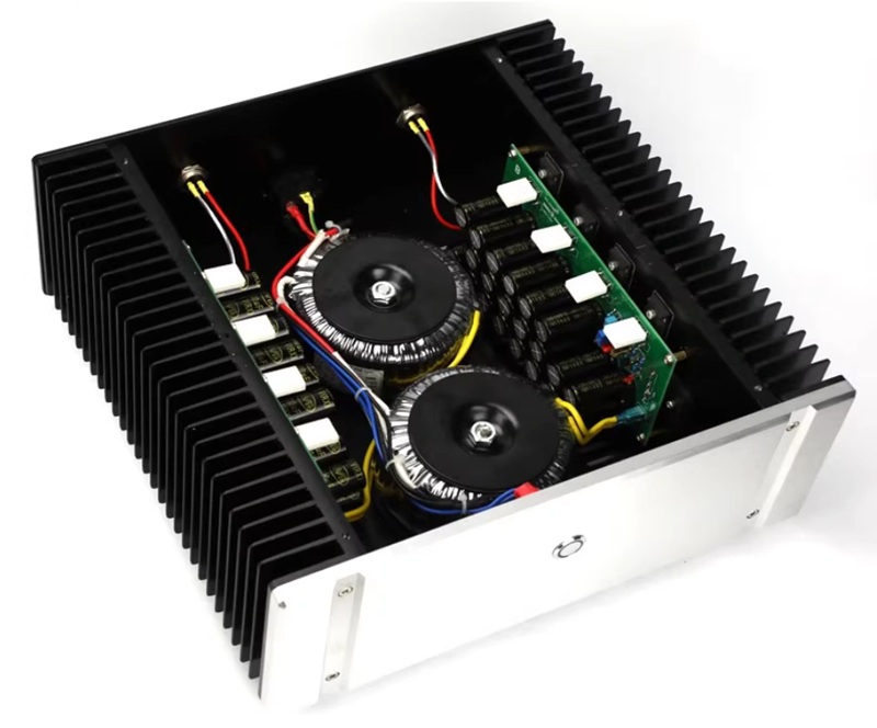
This 200W linear power supply measures in at 320 x 310 x 210mm and costs over $600.
In a typical SMPS, conversion from AC to DC starts with a process called rectification, usually performed by diodes that allow electricity to flow in only one direction. Basic "half bridge rectification" uses this one-way property to capture just the positive portion of the AC wave. More sophisticated "full bridge rectification" employs four diodes to flip the negative portion of the wave to positive, creating smoother DC output with less ripple. Though more efficient, this approach requires more circuit board space and increases component costs.
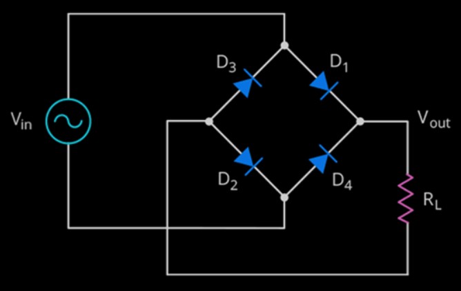
Diagram of full bridge rectification circuit.
During this stage, the AC from your wall, which is a bi-directional sine wave oscillating between positive and negative polarity, is rectified into a unidirectional AC waveform, having its negative cycles flipped positive, or removed altogether, to creating a pulsating DC.
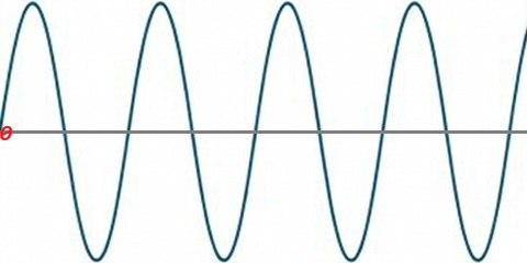
Sine wave as it looks coming from the wall
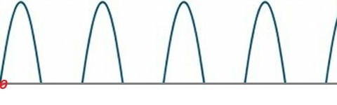
A half-rectified DC waveform. Just the negative voltage has been chopped off.
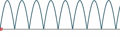
A full-rectified DC waveform. The negative voltage has been flipped to positive.