Yet Another Choice: Interleaved PFC
(Last edited 5/14/2026)
Interleaved PFC is a multi‑phase boost‑converter architecture used in high‑power AC‑DC power supplies to reduce ripple, improve efficiency, and lower component stress. Instead of relying on a single large boost PFC stage, an interleaved design uses two converters operated 180° out of phase. The two boost stages run in parallel, but their switching signals are shifted so that when the switch in the first stage turns on, the switch in the second stage turns off, and vice versa. Because these stages are out of phase, their input‑current ripples partially cancel, significantly reducing total input ripple and enabling a smaller input filter.
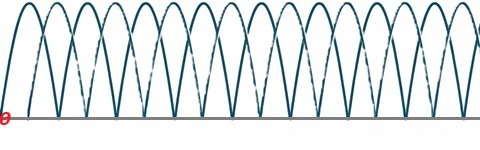
Full rectified DC with a 180° phase shift
The circuit begins with full‑bridge rectification, which converts the bidirectional AC sine wave that is oscillating between positive and negative polarity, into a unidirectional waveform by flipping the negative half‑cycles positive. The waveform is DC in polarity, but AC in shape.
Each PFC phase is a boost converter with its own inductor, switch, current‑sensing element, and diode or MOSFET. A controller IC drives each phase at the same switching frequency but with a phase shift between them. The phase currents combine at the output capacitor, where the offset in timing causes their ripple components to cancel, reducing overall ripple amplitude.
At light loads, efficiency can be improved through phase shedding. The controller monitors load conditions and, when appropriate, disables Phase B so that all power flows through Phase A. This reduces switching losses, gate‑driver losses, boost‑diode (or MOSFET) conduction losses, and magnetic core losses. To prevent rapid oscillation between one‑phase and two‑phase operation, the controller uses hysteresis to ensure smooth, stable transitions.
Interleaved PFC Can Make Noise at low-loads
Unfortunately, a clicking or snapping noise can occur when the once-shed PFC phase is re-enabled.
One source of this noise is the EMI‑filter chokes. Because interleaved PFC relies on ripple‑cancellation between phases, it allows the use of smaller EMI‑filter components. When a phase is shed at light load, this cancellation effect is lost or greatly reduced. The abrupt change in switching dynamics causes a momentary spike in differential‑mode (DM) noise. The higher‑amplitude, lower‑frequency DM component can shift the choke core into a different magnetization point, resulting in mechanical vibration or “snapping.”
A similar phenomenon can occur in the boost inductors. When a shed phase comes back online, the remaining active inductor (e.g., L1 of Phase A) briefly carries the full power that had previously been shared. Inductor current may temporarily double. If the core was sized specifically for interleaved operation, taking advantage of ripple cancellation, the resulting higher peak current can exceed the core’s saturation limit. When this happens, the magnetic material (often ferrite or powder core) undergoes physical deformation due to magnetostriction. The increased current drives the core to a higher magnetic field strength and flux density, intensifying these physical shifts and producing audible noise.