Control & Feedback in an Analog PSU
(Last edited 5/14/2026)
To help regulate output voltages when loads fluctuate, the secondary side must communicate with the primary side. The output voltages are carefully monitored and measured against a precise reference voltage, typically accomplished by an integrated circuit such as the TL431. The IC sends feedback signals back to the primary side's PWM or LLC controller through an optocoupler; a component that uses light to transmit electrical signals across a barrier. This optical bridge is essential because the primary and secondary sides remain electrically isolated from each other.
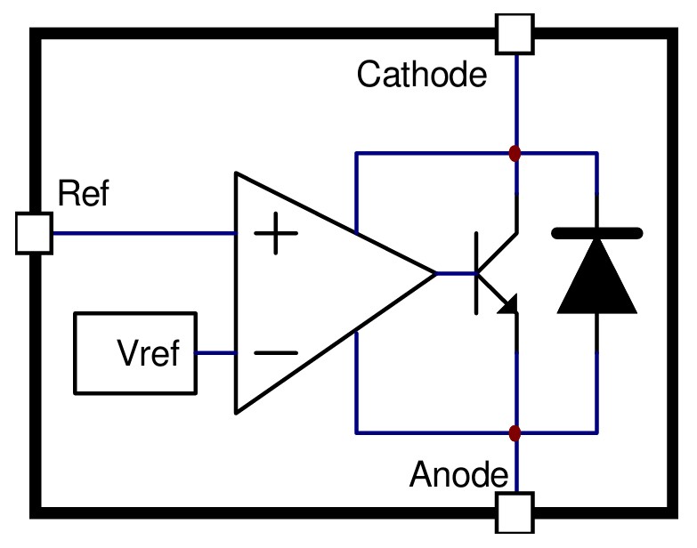
A schematic of a TL-431
When the TL431 detects voltage variations, it adjusts its conductivity accordingly, like a valve controlling flow. This causes the optocoupler' s internal LED to shine more brightly or dim subtly, creating a nuanced optical signal. The PWM controller interprets these light intensity changes as instructions to either increase or decrease the duty cycle, effectively fine-tuning the power delivery to maintain stable output.
Since the power excursions of a modern GPU, such as those of a PCIe 5.x GPU, may cause the voltage to drop before the feedback loop can respond, a non ATX 3.x PSU when used with a GPU that should be used with an ATX 3.x PSU may trip a PSU’s UVP (Under-Voltage Protection. Protections are discussed later in the e-book). For this reason, ATX 3.x power supplies may implement “predictive feed-forward” control. This will be explained in more detail in the section about ATX 3.x later in the e-book.