How do we Correct the Power Factor?
(Last edited 5/14/2026)
In this e-book, I'll focus solely on active power factor correction, as non-PFC and passive-PFC have become essentially obsolete in our industry.
Active PFC uses a boost converter between the rectifier and the bulk capacitor.
The boost converter is controlled so that the input current follows the sinusoidal shape of the AC voltage.
A boost converter is a type of DC-DC converter that steps up (or “boosts”, hence the name) the input voltage to a higher output voltage while reducing the current proportionally; minus the kind of losses expected whenever you make such a conversion. The degrees of losses we see in this circuit is why we see so many different PFC correction topologies. Some are more expensive and complicated than others but are a lot more power efficient.
I’ll briefly touch on the three most common means of correcting power factor; with a high-level circuit diagram to help explain each one.
The most common means, and least efficient topology, is called “AC Switch PFC”. This topology uses transistors controlled by a PFC IC to switch and conduct power only when the waveform is at the correct polarity.
Below is a diagram of an AC Switch PFC circuit:
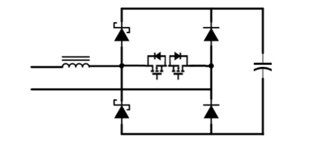
The circuit comprises of an inductor, two Schottky diodes, two general rectifier diodes, two N-Channel transistors and a bulk capacitor.
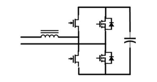
The next type of power factor correction topology we’re going to show is the totem-pole:

Not that kind of totem pole!
The term “Totem-pole” in Totem-pole PFC comes from the physical arrangement of the semiconductor devices in the circuit. In a totem-pole PFC topology, the transistors are stacked vertically in a series configuration, similar to how the figures are stacked on a traditional totem pole. This vertical arrangement allows the circuit to perform bidirectional current flow and achieve high efficiency in power conversion.
Yeah. I don’t see it either.
No, really. I’m kidding. The totem-pole refers to the two stacked FETs on the right of the diagram. These are high-frequency switchers, what we would call a “fast FET”. The two components on the left can be either slower FETs, with longer switching speeds, or a fast diode like a Schottky.
The last one I’m going to show is the active bridge. Active bridge is cool because it not only corrects power factor, but it also replaces your rectification stage.
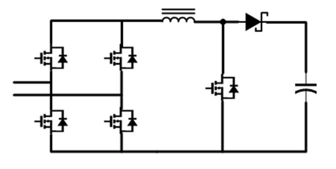
In this diagram, we have four fast FETs in a bridge, a lone slow FET and a Schottky. A controller is used to sense the AC voltage and current and adjust the switching pattern accordingly. The boost inductor is in series with the AC input, and the active bridge controls the energy transfer to the DC bus.
At the end of the day, all three of these do the same job. They ensure that mostly real power is used. Whatever apparent power that is supplied is like power that is supplied that cannot be used, so while your power supply may be of Platinum or Titanium efficiency numbers when you divide the DC output by the AC input numbers, you may be eating up unused apparent power that is costing you money on your electric bill which can matter in commercial or industrial billing contexts where apparent power or demand charges apply.
So why are there choices?
While we can hope for a .99 power factor most of the time, we will experience some loss of power in the process. Your typical switch PFC is cheaper, and pretty easy to work with given its maturity. But it’s not as effective as other topologies as you may only achieve a 98% efficiency. I know that sounds pretty good, but the parts used get pretty hot, so you’ll need to reserve some space for some beefy heatsinks.
The totem-pole allows you to bump that efficiency up to 99%. But to do so using MOSFETs introduces several significant challenges. Difficulties arise primarily from their inherent gate capacitance, the need for precise gate driving, and the management of parasitic effects and EMI that becomes prominent at higher switching speeds. While switch PFC can be driven with an analog controller, you’ll need an MCU for totem-pole. If you’re considering totem-pole, I highly recommend using GaN FETs or SiC. Fast switching is way more stable using these transistors as opposed to using MOS. And these days, you can get FETs with integrated gate drivers to help simplify and stabilize the circuit.
Active bridge is a topology I like to use for really high wattages. It’s hard to justify its cost at anything below 1200W, but at higher wattages, you’re replacing the rectifier and typically achieving efficiency of 99% or better.