The DC Bus and Bulk Capacitor
(Last edited 5/14/2026)
Earlier chapters examined capacitors in detail, including the X and Y capacitors used in the PSU’s input filter. Now let’s focus on the large capacitor on the primary side. This cap is often called the bulk capacitor or the primary capacitor.
After the PFC stage, the DC must be both smoothed and stored for downstream circuits, and that’s exactly what bulk capacitors do.
As discussed in the ripple chapter, ripple can stem from residual line AC or switching artifacts, and bulk caps significantly reduce this unwanted variation. They also hold charge to ride through brief AC interruptions; the larger the capacitance, the longer a PSU can maintain output during a brown-out. This ride-through capability is expressed as the PSU’s “hold-up time,” measured in milliseconds at a specified load. For instance, ATX standards require a 16.6ms hold-up at 100 % load. This is equivalent to losing one cycle on 60Hz mains (since 60 cycles occur per second).
As for the voltage used for the capacitor; I see a lot of people incorrectly assume that we’re only dealing with operating voltages within the PSU that are equal to that of the mains’ voltage. But in reality, we are working with voltages in the neighborhood of 380 to 420V. The reason for the higher voltage is to support the voltage at the highest peak, called the “Vpeak”, of the AC wave. Let’s say the AC voltage is 264V. The formula we use is “Vpeak = VRMS x √2”. VRMS is 264 and we can round √2 to 1.414, we can calculate 264 x 1.414 as 373.296. This is where I would use at least a 400V capacitor. Obviously, we typically see bulk cap voltages much higher than 400V. This is because we always want a considerable amount of margin in our designs… unlike the design of the 12VHPWR connector.
Why a UPS Without a Pure Sine Output May or May Not Be An Issue
UPS devices with an output waveform that is square or stepped/simulated/modified (three terms for the same thing, but moving forward I’m going to use “stepped” because the wave form looks like steps and I like that) can sometimes clash with power supply units that have active power factor correction. First, I want to put everyone’s mind at ease and tell you that a non-pure sine wave UPS is not going to blow up your APFC power supply. The PSU is smart enough to just shut down if it doesn’t like what’s going on. The compatibility issue stems from how these non-sine waves linger at maximum and zero voltage points. In contrast, true sine waves flow continuously through their cycle, touching zero voltage instantaneously when changing direction and reaching peak voltage just momentarily before moving on.
When a square or stepped UPS waveform lingers at zero or peak voltage, the PFC controller does not think “this is a square wave.” Instead, it misinterprets that behavior as one (or more) abnormal mains conditions it was explicitly designed to protect against. When the square wave is lingering at zero, the PFC controller may see a gap in power. And when it lingers at peak voltage, it may think “I’m being asked to draw too much current for too long. The line voltage is not changing when it should. Something upstream is wrong.”
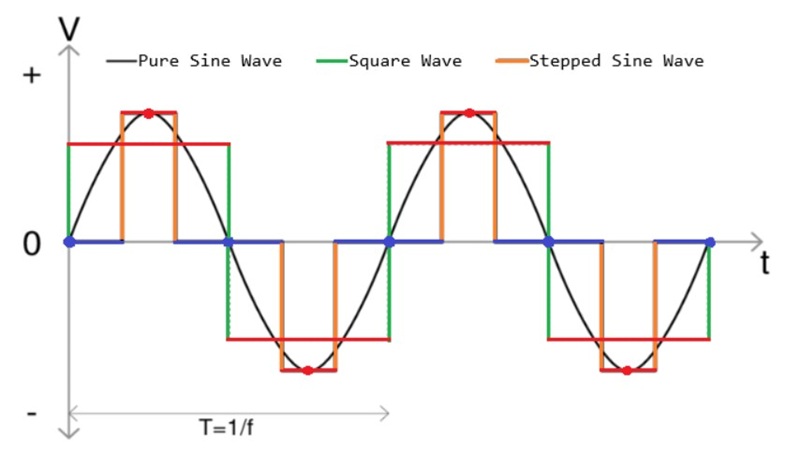
In the above drawing, I’ve made the peaks red (lines and dots) and the zero intersections blue. As you can see, the square wave and stepped sine wave linger at the peaks far too long compared to the pure sine wave.
The same sort of situation happens when that stepped sine wave lingers at zero for too long. The active PFC controller again doesn’t “see a square wave.” Instead, it interprets that behavior as a pathological loss of mains energy at exactly the worst possible time in the cycle. Many controllers interpret this as a brownout or a missing half-cycle.
Fortunately, it is very rare to have a power supply that cannot handle a non-sinusoidal AC waveform. Most analog controllers for at least the last decade, like the Champion CM6800TX, have featured an average-current mode that continuously senses the rectified input voltage and not just the peaks. In this case, the current reference is proportional to the instantaneous voltage, whatever its shape. And, of course, a digital / firmware-based PFC controller, like Texas Instruments’ TMS320F2802, would have no issue either.