Using a "Fog Light" Relay to turn on a second PSU:
Let's start by getting all of our parts together.
First we need a 4-pin, 30A,
12V relay. These will have four to five terminals on them labeled
85, 86, 87 and 30. These are VERY common in
junkyards. So if you have access to a U-Pull-It yard, you can
score one for free. Look in the VW/Audi section. The older the car
the better.
The fuse panel is just above the clutch pedal.
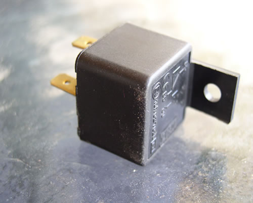
They're typically referred
to as "fog light relays" because
they always come with fog light kits. Essentially, a 12V current
from the ignition (the car's ignition coil) comes into terminal
85, which
then goes through a coil and then to a ground on terminal 86.
When this happens, whatever is on terminal 30 (usually voltage
for the fog lights)
is bridged over to terminal 87 (the fog lights.)
Some of these relays may have an 87A terminal. This is where the voltage
on terminal 30 goes when 85 is not energized. We don't need this terminal,
so don't worry about it. If you can't find
one in a junk yard, you can buy a new one at an auto parts store
for as little as $5 or $6. You'll also need four female disconnects, preferably insulated. These
are going to get crimped to your wires and pushed onto the terminals
of the relay. Typically, we all have these laying around the garage because
they can be bought in boxes of 100 at a time. If you can't find your
box of female disconnects, go to the same auto parts store you bought
the relay from and buy a box of 5 for $3. Now we need
something we can plug into our "main" power
supply. Something that will take 12V from the power supply
to terminal 85 on
the relay. I use a simple four to three pin fan connector.
I cut off the three pins so now I only have a four pin Molex with
a 12V and ground
lead coming off of it. I crimp a female disconnect on to each
of the two wires. 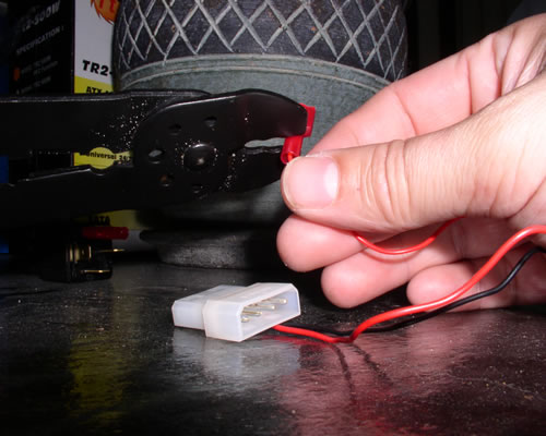
Here I'm crimping the terminal to the end of a wire from the
fan Molex. I suggest using insulated terminals, but if you
use cheap crimpers (like me. I couldn't find my Kleins) I
suggest removing the insulation before doing the crimp, then
sliding the insulation back on.
Here's my fan Molex hooked up to 85 and 86 of the relay.
Finally, we need to get the turn on signal from the axillary power supply
to the relay. The cheapest way to do this is with two wires and two wire
taps. Put a tap on the green wire and a tap on a black wire and put a
female disconnect on the other end. I'm going to be a little fancier. I have a 20-to-24 pin ATX
adapter that I'm not using. I cut the green and a black and
put my disconnects
right on the wires. Bad thing about this is that I now have
22 other wires just hanging with nowhere to go. What I'll eventually
do is just
take a pin extractor and pop all of the unused wires out of
the ATX connector. The end result will be a female ATX receptacle
with two wires coming
out of it: A black and a green. So take the 12V lead from
your fan Molex and put it on terminal 85 of the relay. Take the
black wire and put it on terminal 86. Now take the
green wire from the axillary PSU and terminate that to terminal
30. Take the black from the axillary CPU and terminate that to 87.
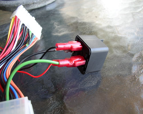
Here we see the green and black wires from the ATX
connector going to terminals 30 and 87. That's it. Now when the main PSU is turned on, and the Molex is live,
the relay is energized and the green wire on the axillary power supply
is grounded in turn telling that power supply to turn on. 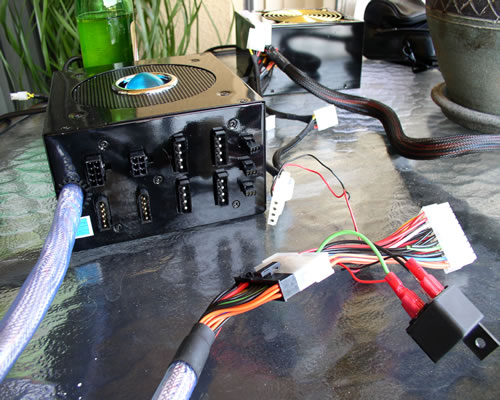
The Thermaltake in the back in going to energize the relay via the
fan Molex. This will then bridge the circuit of the green and
black wires of the 20-to-24 pin adapter that's plugged into the
Aerocool. So what we have here is; the Thermaltake is the main
PSU, turned on by the motherboard, and this in turn turns on
the Aerocool which may be used for a Peltier, fans, CCFL's, pump,
etc. Make sure you don't load the 12V up too much without having
something on the 5V as well (even a dummy load resistor) or your
12V will go out of spec!!
|